The Anti-Ground-Loop Tail Skid
A ground loop is when the tail of the aircraft loses directional stability and rotates about the horizontal axis of the aircraft. This leads the tail to spin around …change places.
In design, the Fork Steering Axis, Head Tube Angle (Caster), Crown Offset, Reduced Offset, Steering Input Offset, Steering Input Moment Arm, Wheel Diameter, Trail, Rake, Slop, Slew and Suspension are all manipulated to change where and how the Contact Patch interacts with the ground, which changes steering, follow and flop characteristics.
Due to a steering phenomenon known as flop the head tube (or whatever its attached to…like the fuselage) raises and lowers as the contact patch rotates back and forth around its axis. Problems occur when gravity wins, at the worst possible moment, and it seeks out the lowest position. Some tailwheel designs can cause an aircraft to turn more than expected, some can cause them to shimmy like a grocery cart.
Poor Speed Balanced Geometry may be responsible for miscommunication between man and machine and result in turns that corkscrew with increasing rotational velocity without additional input from the pilot. Generally, the more the turn has accelerated into the arc, the more difficult it is to apply adverse torque to recover.
Ground handling characteristics of a tailskid are quite different than those of a tailwheel. A proper designed tailskid becomes directionally stable when a retarding force is applied behind the Centre of Gravity (CG), which damps directional divergence. In addition, the size, angle, and location of a tailskids contact patch can be more easily manipulated and is not dependent on wheel diameter. Low speed Low Mass flying or gliding machines are normally operated from grass surfaces where the retarding force is quite strong, minimizing directional divergence, however, tailskid maintenance is much higher than a tail wheel.
A Tailwheel System, on the other hand, is not as design friendly. They are not as apt to become directionally stable, as the tailwheel offers little retarding force. In addition, some suspension systems complicate contact patch geometry of the tailwheel system, which relies more so on a heavy foot, stick back rudder control, a combination of tailwheel steering, differential braking…and an experienced, knowledgeable, and competent pilot.
The Skonkwerks Suspension Tailskid has an optimally located contact patch with minimal flop and migration for 3” to 4” of suspension. It is intuitive, tracks straight, ignores slight rudder inputs, and turns wide without short bursts of full power. It is extremely lightweight, and the steering slew can be adjusted by changing the durometer of the elastomeric bushing. The travel has a sensitive top stroke, supportive mid-stroke, and a strong bottom out resistance. With its UHMW skag, (wear strip for the non-snowmobiler) it can be operated on asphalt and dirt with little, if any noticeable handling deficit. Estimated skag life on asphalt is 4 miles.

Tail skid mandrel, side plates and presser. 
One of the skids is Kevlar covered Carbon. Turns out its not needed. 
Finished skids before the machining. 
Skids with wear plates attached with 3 tech screws from behind. 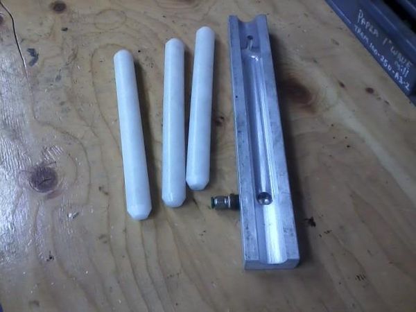
Vacuum jig to hold onto the 1″ dia. UHMW rod. 
Machining to half round. 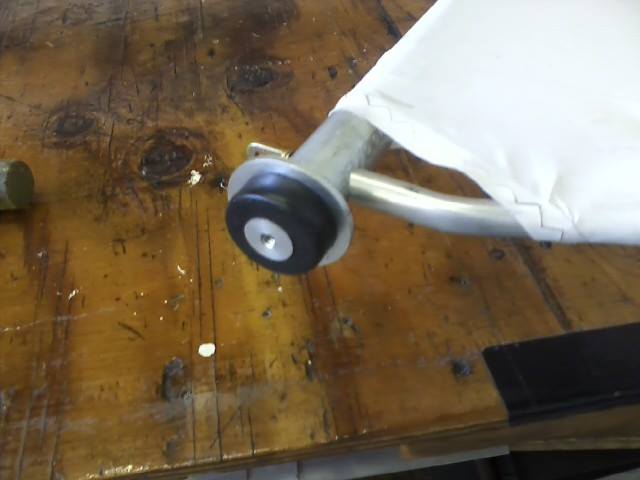
The elastomeric steering bushing on the bottom of the rudder steering post. 
The skid fitted on the rudder steering post. The softer the bushing the more slew or slower response in the steering.
Carbon Tube Project
This project is to explore the construction of carbon fiber tubes made in a wet lay-up process on a non-tapered aluminum mandrel. Traditionally tubes are made from outrageously expensive pre-peg fabric on tapered mandrels which can cost upwards to $10,000 USD (quoted in 2019). By adjusting the five variables listed below it is believed that the fiber/resin ratio can be manipulated which directly affects the strength, flexibility, and remove-ability of the resultant tube. It is also believed that with proper documentation, once an acceptable protype is developed, the process will be easy to re-produce, lending itself to economical carbon tube production in lengths to 20’ by most experimental aircraft constructors.

The amount, location, make-up and orientation of the carbon material used.
The type of resin used.
The internal mandrel pressure.
The internal mandrel pressure.
The internal auto clave pressure (external mandrel pressure.)
Following is a preliminary schedule of events that should unfold and transition smoothly. Once the resin is mixed the entire process needs to be finished in about twenty minutes which is an acceptable resin pot life.
Lay out and cut fabric.
Weigh and record fabric weight.
Mix resin.
Start timer and begin to wet out.
Roll onto mandrel.
Remove (lift) mandrel from table.

Clean table.
Lay-out pre-cut peel ply.
Roll peel ply onto mandrel and tape
Remove mandrel (lift) from table.
Clean Table.
Lay-out breather.
Roll breather, tape if necessary.
Lay in vacuum tube.
Remove (lift) mandrel from table.
Clean Table.
Lay out pre-cut vacuum bag.
Roll vacuum bag onto mandrel and tape.
Put on lower end and start vacuum pump.
Pull vacuum and inspect.
Put on nose cone and slide into auto clave.
Fasten upper and lower ends and hydraulic lines.
Lift vertical.
Attach hydraulics and start pump.
Attach auto clave pressure line and set.
Remove vacuum pump and vent lines to atmosphere. (No longer needed.)
